API 6A (ISO 10423) 6BX flanges are used extensively in high pressure sub-sea oil and gas installations. The ability of these flanges to transmit bending moment and axial tension when correctly made up is given in the capacity charts provided in API 6AF for service temperatures up to 121°C, adequate for most services.
When carrying out calculations to substantiate the design of these flanges FCL are often questioned as to why the predicted capabilities to transmit bending moment an axial tension are significantly less than expected based on the charts in API 6AF. This case study identifies the principal reasons for this reduction in capability, i.e. material selection, line pipe dimensions and cathodic protection of flanges in duplex stainless steels.
API defines the strength characteristics of materials employed in the flanges based on their tensile and yield strength at ambient temperature. Materials are grouped into four strength designations, 36K, 45K, 60K & 75K and API identifies the strength designation associated with different flange ratings. Thus for 5000, 10000 and 15000 psig rated flanges API requires that materials of strength designations 45K, 60K and 75K respectively are employed. Materials commonly used in sub-sea applications are carbon steels, A694 F52 and F65, as well as duplex and super duplex stainless steels A182 F51 and F55. These materials have strength designations of 36K, 45K, 60K and 75K respectively. Thus it can be seen that strictly only flanges in super duplex stainless steel are of sufficient strength to be used in 15000 psig rated flanges and that A694 F65 can only be used for flanges rated at 5000 psig. Use of a weaker material will obviously reduce flange capability.
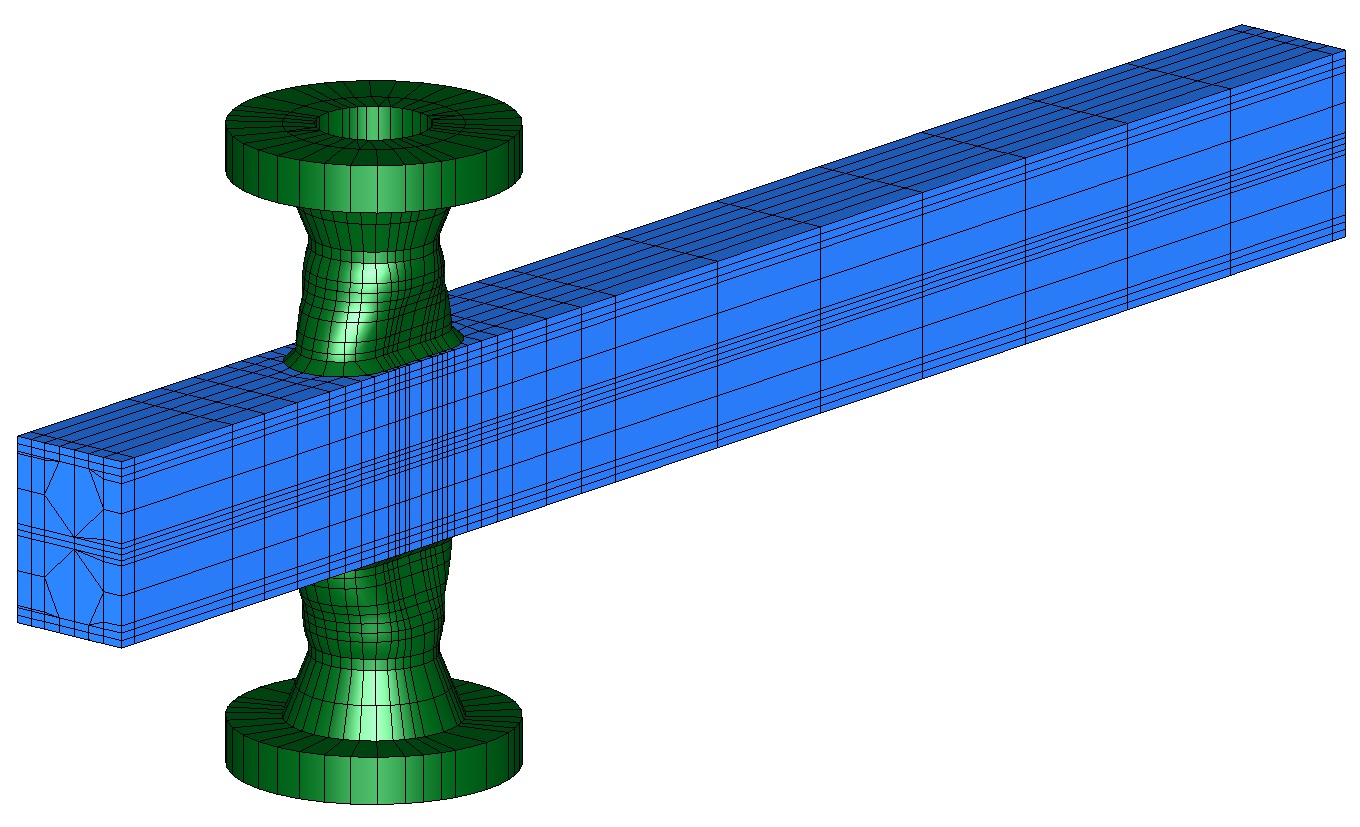
API flanges are designed with bores which are equal to the nominal flange size and not to be matched with standard B36.10 pipe sizes which generally results in a flange with a reduced bore. Reducing the bore of the flange increases the bending moment developed in it and can lead to higher stresses and a reduction in capability.
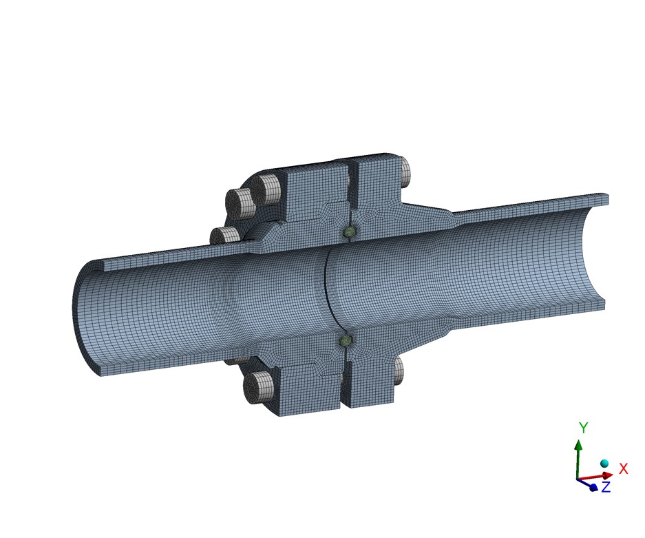
Flanges in duplex and super duplex stainless steels installed sub-sea are susceptible to Hydrogen Induced Stress Cracking (HISC) if afforded cathodic protection. To minimise the risk of HISC reduced stress limits are imposed in DNV-RP-F112. These limits depend principally on the austenite spacing found in a micrograph of the material and the location under consideration with respect to the weld between the flange hub and line pipe.
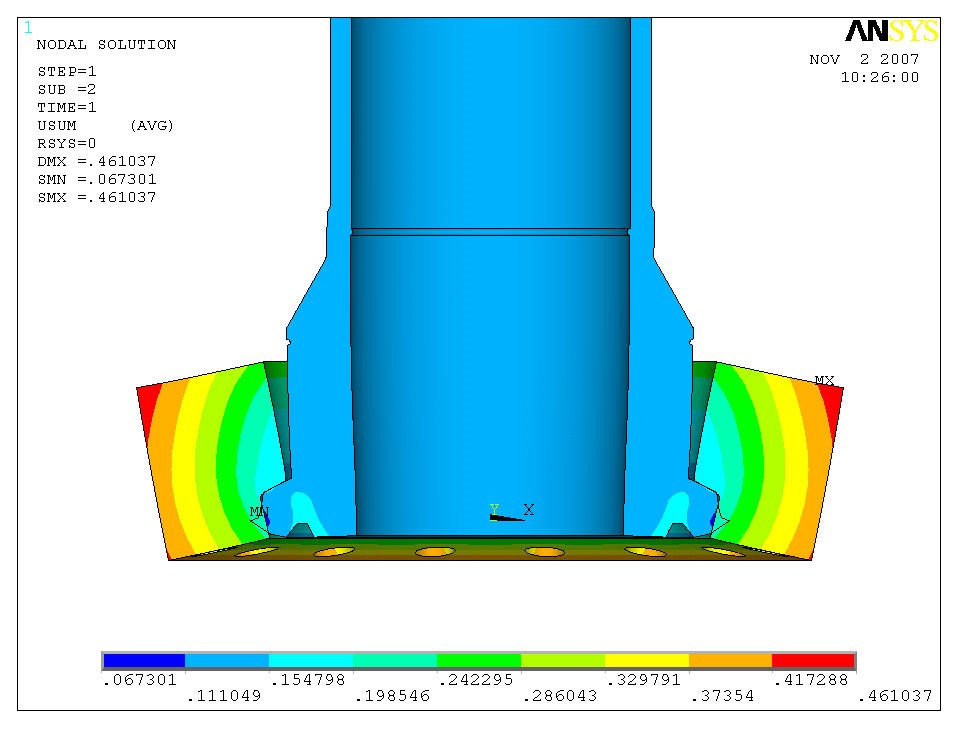
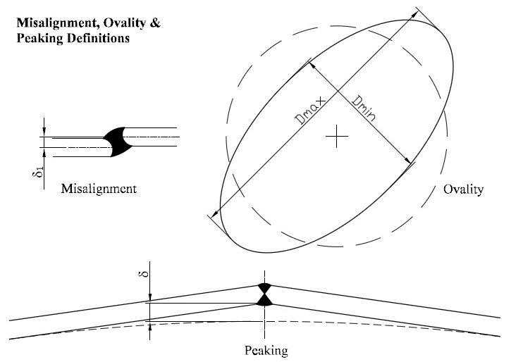
In general terms DNV-RP-F112 requires that the membrane plus bending stress is limited to approximately two thirds of the material yield strength at temperature. Following rules in ASME Section VIII Division 2 Section 4.16 the allowable longitudinal hub stress is equal to the yield strength of the material when API stress limits are adopted. The DNV recommended practice reduces the allowable stress by one third. It is also necessary to account for the additional bending stress at the hub to pipe weld as a result of misalignment, including that which is within the tolerance prescribed in the adopted piping code, which will reduce flange capability still further.
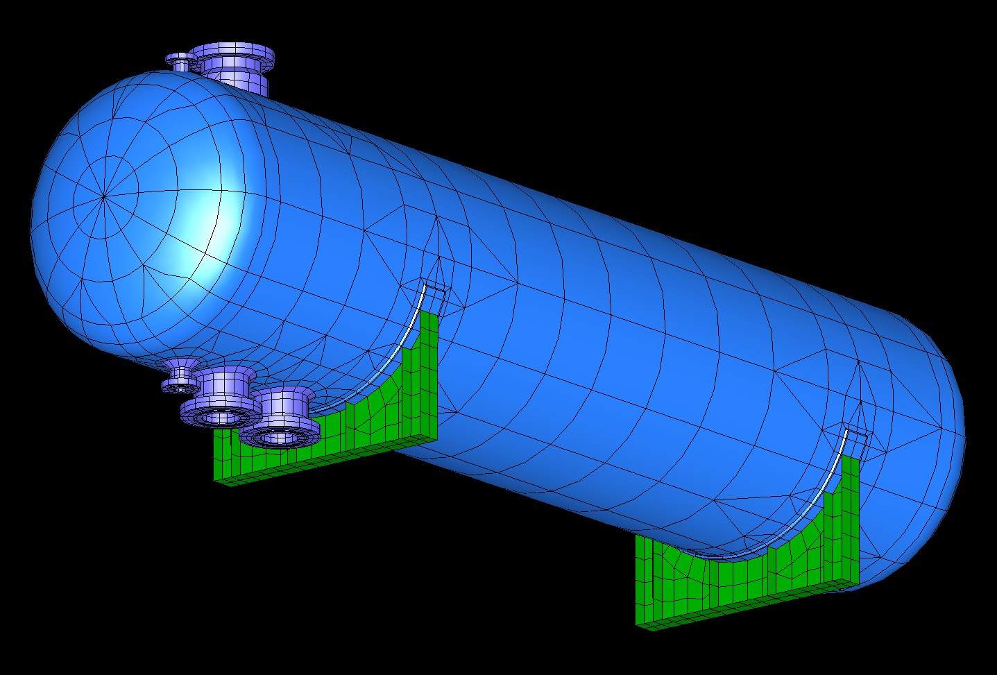
It can therefore be seen that these three factors play a significant part in reducing the capability of API flanges below that given in API 6AF, particularly for those in duplex and super duplex stainless steels when used sub-sea. While code calculations can be used, the use of FE stress analysis is recommended to maximise flange capability particularly where stress limits prescribed in DNV-RP-F112, which are based on linearised stresses from such analyses, are to be satisfied.
Added November 2025.
API 6A (ISO 10423) flanges do not have specified limits on external loads and these should instead be established by those responsible for the design of the flanges. Work was carried out in 1987 by Stress Engineering Service (PRAC-86-21), for API, to determine the capabilities of API flanges under combinations of loading. This work was subsequently summarised in API 6AF, which presented a series of rating charts to be used for API 6A 6B and API 6A 6BX flanges. The charts presented therein indicate the limit on bending moment that can be accommodated for a given combination of bore pressure and axial loading. Charts are organised by flange rating and bolt make-up stress. However, these charts, while helpful indicators, cannot account for factors such as the risk of HISC or modifications to the flange geometry to suit the attached piping. As such, bespoke calculations should be calculated to address these factors and establish external load capacities for the specific use case. Finglow specialises in carrying out flange design on this basis.
By using design methods in ASME Section VIII Division 2, PD 5500 and API 6A in combination with DNV-RP-F112 as necessary. Stress limits for the combined loads are calculated based on the material of construction of the flange for the operating and test conditions.
API 6A (otherwise known as ISO 10423) is a flange standard, similar to ASME B16.5 and B16.47. Within API 6A, Type 6B flanges cover low pressure (below 5ksi) and smaller sizes (up to 21¼″, depending on rating) while Type 6BX flanges cover increased pressures (up to 20ksi) and a flange size range from 1 13/16″ up to 30″. The key difference between 6B and 6BX flanges is that 6B flanges are designed to make-up via a metallic ring joint, and not for face-to-face make-up, and shall employ R or RX type gaskets, whereas 6BX flanges may make up face-to-face (though not necessarily) and shall employ BX type gaskets.
HISC (hydrogen induced stress cracking) is a type of mechanical failure where hydrogen atoms diffuse into a metal causing changes in the structure of the material. This influences properties such as strength and ductility causing flaws to propagate more easily through the material causing fractures.
It can be of particular concern for subsea flanges in duplex material when subject to cathodic protection, where the recommended practices in DNV-RP-F112 should be followed to mitigate the risks of HISC.
API 6AF charts do not account for factors such as the risk of HISC or modifications to the flange geometry to suit the attached piping. As such, bespoke calculations should be carried out to address these factors and establish external load capacities for the specific use case. FCL specialises in carrying out flange design on this basis.
Typically high-yield carbon/low-alloy steels, such as ASTM A694 F52 and F65, as well as duplex and super duplex stainless steels, such as ASTM A182 F51 and F55.
Cathodic protection is used to prevent corrosion of metallic subsea structures, including pipelines. However, this also produces hydrogen at the surface of the metals which increases the risk of hydrogen induced stress cracking (or HISC) at locations of elevated stress in duplex and super-duplex steels.

Please use this form if you have any questions about our capabilities or would like to obtain a quotation.
Alternatively, you are welcome to call or contact us by e-mail.
+44 (0)1992 585450 enquiries@finglowconsultants.co.ukYour enquiry has been safely and securely received. Our office is open weekdays from 9am to 5pm - you can expect a response during the next 2-3 working hours.