The traditional method of proving a pressure vessel or heat exchanger design is to carry out mechanical design calculations in accordance with procedures in established design codes.
While the so-called design-by-rule approach is sufficient in the majority of cases there are sometimes features of the design or aspects of the process operation which, because they are not covered by the available rules, necessitate the use of design-by-analysis methods to demonstrate code compliance.
Typical applications of the design-by-analysis method are as follows:
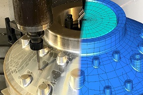
Finite element stress and thermal analysis is carried out using ANSYS and CREO/Simulate finite element programs. Structural analysis capabilities include static linear and non-linear stress analysis, forced vibration and modal analysis, and fracture mechanics. Thermal analysis capabilities allow complex transient or steady state temperature distributions to be evaluated for thermal design optimisation purposes or for subsequent thermal stress analysis.
All finite element analysis work is undertaken by FCL staff with qualifications and experience consistent with NAFEMS (National Agency for Finite Element Methods and Standards) Personnel Accreditation guidelines.
It is our view that the value of design-by-analysis work depends not only on the accuracy of the analysis but also on the interpretation of results and the manner in which the findings of the work are reported. FCL’s knowledge in this area is invaluable, both in minimising the need for client involvement and in achieving timely approval from third parties.
The use of design-by-analysis methods in pressure vessel and heat exchanger design continues to grow with development of the underlying European and US design codes. FCL, with the in-depth knowledge of these codes at its disposal, aims to maintain its position as one of the UK’s leading suppliers of design-by-analysis services to the pressurised equipment industry.
FAQs
Added January 2026.
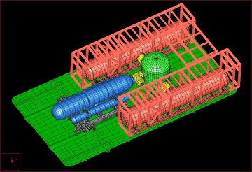
Design-by-analysis refers to the use of computer-based simulations or mathematical models to evaluate the adequacy of a design. Typically, the component geometry is defined in a computer aided design (CAD) model, appropriate material properties and loading/constraint conditions are applied to simulate the component and the expected loading, and a detailed analysis is performed using computer aided engineering (CAE) software to evaluate the deflections, stresses and/or temperatures arising in the structure for assessment against defined limits.
In the case of pressurised equipment, design-by-analysis methods are typically applied when aspects of a design fall outside the scope of the chosen design code. Common examples are large rectangular openings, nozzles located in the knuckle regions of dished ends and special flange designs. Design-by-analysis methods may also be applied to assess temperature gradients in components subject to transient thermal behaviour, or to provide an accurate prediction of fluctuating stress levels where cyclic service requires a fatigue life assessment.
FCL primarily uses ANSYS for finite element stress and thermal analyses. We have decades of experience using this software to produce 2D axisymmetric, 3D shell or 3D solid models of varying levels of complexity, and always seek to achieve a high quality mesh with the necessary refinement in areas of interest to produce accurate results. We also have substantial experience in using Creo Simulate (and legacy versions of this software released as Pro/MECHANICA Structure and Thermal), which utilises P-element technology to provide high levels of convergence with relatively coarse meshes.
Yes, we regularly assess nozzles, flanges and large openings for specified nozzle loads. This ranges from using design-by-rule methods provided in ASME (where stresses are calculated using the methods in WRC 107 & 297) or PD5500 Annex G, through to the use of design-by-analysis methods. In cases where nozzle loads are unknown, we can derive an appropriate set of standard nozzle loads based on the specified materials and temperatures, which compares closely with the standard loads recommended by a number of operators in the petrochemical industry. We are also able to prepare piping flexibility analyses to calculate accurate nozzle loads from attached piping.
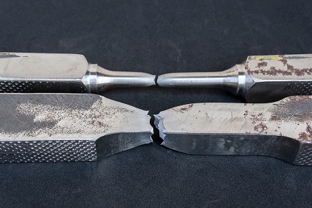
We have extensive experience carrying out both linear eigenvalue and nonlinear buckling analyses, which has included investigation of the behaviour of stiffened cylinders subject to external pressure loading, where imperfections such as corrosion and out-of-roundness can have a large impact on the safe operating limits. We also have experience using modal analysis techniques to estalish the natural frequencies of a given structure, which has enabled us to provide solutions where excessive vibration is reduced and resonance avoided. Finally, we also have extensive expertise in using design-by-analysis methods to provide accurate predictions of stress on which to base fatigue life and defect assessments for both new and existing equipment.
We are able to carry out design-by-analysis compliant with ASME Section VIII Division 2 Part 5, PD 5500 Annex A, and the European harmonised standard EN 13445. Our finite element analysis work is also undertaken by staff with qualifications and experience consistent with NAFEMS (National Agency for Finite Element Methods and Standards) Personnel Accreditation guidelines.
The specific needs are likely to vary on a project-by-project basis, but in general you would need to provide fabrication drawings containing sufficient detail to enable us to produce an accurate model. Ideally, these drawings should be fully dimensioned with information on component thicknesses, weld details, materials and corrosion allowances. To enable us to establish the required scope of the work and to prepare appropriate analyses, you would also need to provide information on design conditions such as pressures, temperatures, external loads and environmental information.

Please use this form if you have any questions about our capabilities or would like to obtain a quotation.
Alternatively, you are welcome to call or contact us by e-mail.
+44 (0)1992 585450 enquiries@finglowconsultants.co.ukYour enquiry has been safely and securely received. Our office is open weekdays from 9am to 5pm - you can expect a response during the next 2-3 working hours.